By Knut Wille Norway - '78 Darmah
What you will need is:
7 ea. constant-voltage regulators of the type 7805 CV or 78S05CV or equal (approx.cost:1USD each) which give out the constant voltage of 5 V. They accept up to 30 V in, but always reduces the output to 5,0 V. That's the clue; whatever voltage in, you'll always get the correct voltage on the LEDs.
I guess you can get them at a local radio/hobby-electronics shop
6 ea. green 5 m/m diameter LEDs. 2,1V for the NEUTRAL- and LIGHT -indicator light.
6 ea. red 5 m/m diameter LEDs. 2,1V for the GEN- and STAND-indicator light.
2 ea. yellow 5 m/m diameter LEDs. 2,1V for the flasher-indicator lights L & R.
3 ea. of the colour you prefer for the HIGH-BEAM-indicator light. (you can't get blue, so I used yellow)
Correction made on Jan. 10th. 1999.:
(Now blue LEDs are available. I saw them on a US- web-site. Can't recall which one. Try to seek for it using Alta Vista or similar search-engine. I'm sure that as they now are available in the colour blue, an electronics shop can get hold of them for you )
7 ea. resistors, 1/8 Watt, 280 ohm , colour-coded with a red, gray and brown ring from one end (in that order) (You can substitute here; I took a chance, and chose 180 ohm (wearing rings of brown, gray and brown ) beeing conscious that I did it in order to get a very slightly brighter light at the sacrifice of life-length of the LED.)
VERO-board (it's a kind of circuit-board which is pre-drilled and have straight copper-leads on one side.) approx. 8 x 20 holes. You might need to buy a larger board, but you can always use it to connect more LEDs in one lamp, or maybe I'll come up with something later on which you can use as replacement for something else.....
Soldering bit (30 Watt).
Soldering tin alloy.
Small wire-cutter.
Heat-shrinking plastic-tube of at least two sizes .To fit over the VERO-board and over the soldered wire-connections.
A piece of good quality (a brand that doesn't unwrap neither in the cold nor in strong heat at summer) electrical insulating tape.
PLEASE BE AWARE : The longest leg of the LEDs are to be connected to the positive terminals ("+"). Nothing will burn, but you won't make them light if you position them the other way.
The first thing I did was to loosen the whole unit and remove the ignition-switch from the aluminum-unit. Having done that, I marked all the wires carefully to which lamp they were connected, and removed them from the lamps. Now I had to concentrate on removing the lamps from the unit and carefully chip the interior out.
When all the lamps were out, I cut the length of the glasses to make space for the new items. (I cut off approx. 3/8", just beneath the "lips" holding the glass in place.)
Now the time had come to fit the new stuff... I glued 3 LEDs of the same colour to the very bottom of the glasses
NB !! (USE CLEAR 2-COMPONENT EPOXY GLUE !!!! I, AT FIRST TRIED USING PLASTIC-GLUE, AND THE AREA WHERE THE GLUE TOUCHED THE LENS TURNED KIND OF "MILKY").
(You might want to glue the LEDs together 3 in a row before you fit them , it's easier to make them align in the housing that way... sand them a little to get good contact to the neighbour-LED).
When the glue had dried, I soldered a piece of VERO-board (2 holes x 4) on top of them leading the terminals through the board (2 x 3 holes for the LEDs, 2 x 1 for the new connecting wire)
I then soldered two pieces (+ and -) of wire (about 1' long) to the end of the board . I hope the pictures will show how I did.
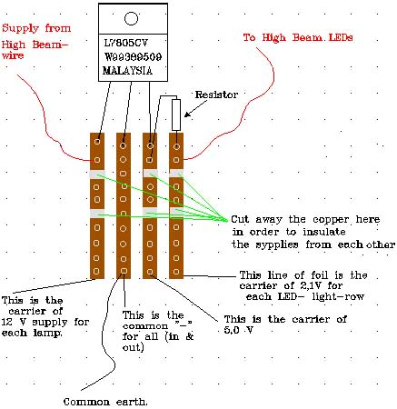
Then I used a piece of VERO-board with 4 x 14 holes and carefully soldered the voltage-regulators and resistors to it like the drawing (and photo) shows. I then drew the new wires to the old ones and soldered them together. Then I covered each soldered wire separately AND then the Vero-boards with heat-shrinking plastic tubing to insulate them.
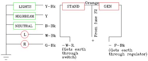
The wires from the "GEN"-lamp and "STAND"-lamp has a common "+" of the orange colour. The "-" is "PINK/BLACK" for the "GEN", and "BLUE/BLACK" for the "STAND".
The LONGEST leg of the LED is to be connected to the "+"s. (i.e. the wires coming in through the bottom of the housing).
The colour of the "HIGH BEAM" light has to be substituted with an other colour ( I used yellow LEDs).
If it's hard to figure out what I mean and how I've done it, just ask ! I'll be pleased and do my best to help !! Have fun !!! ;-)
AND:
I've changed the location of the lights in order to get more room inside. (I.e. the red lights at either side of the ignition-switch, and the others above it.)
AND:
What I didn't include in the above recipe was that you CAN substitute some of the LEDs with other kinds of LEDs. (If you are in doubt, ask the salesman/shopsuperv. for help) I substituted the red LEDs in the GEN-light for two red LEDs with a lens on them. They give brighter light. You can also get hold of blinker-LEDs. I used 3 blinker-LEDs in the STAND-light. It was just for the case of ease that I recommend equable LEDs. All the other LEDs are also 2.1 V.
If you prefer to use the red LED with the lens on it, you have to sand them off hard to get them into the old glass ( I had to sand them square in shape to get them inside)
AND:
And if you've got trouble from rain/water leaking inside the lamp-housing, try to use some drops of clear silicone sealant round the lamp-glasses as you fit them in the housing.;-)
This is a tip in order to solve a problem, and I don't take any responsibility for your use of it. My intentions are well ment, and I hope the above recipe solves your troubles with the Darmah / Pantah / MHR - related problem to the blowing of "idiot"-light bulbs :-)