Dellorto Motorcycle Carburetor Tuning Guide

  ducatimeccanica.com - home
3.7 Acceleration

Every time the throttle is opened suddenly, the air speed in the barrel drops.

In two-stroke engines this does not upset good engine running, but in four-stroke engines this drop in air speed causes the atomiser to deliver insufficient fuel.

For this reason, on large-diameter Carburetor s for four-stroke engines, an accelerator pump enrichment device is fitted.


3.7.1 Diaphragm accelerator pump
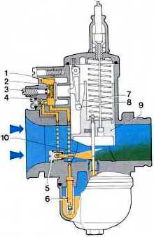


fig. 27


As shown in figure 27, on opening the throttle slide (9), lever (8) controlled by a special cam (7) cast into the front of of the throttle slide, acts directly on the pump diaphragm ( 1), I held out by the spring (2).

This diaphragm, through the delivery valve (4) and pump jet (5), pumps fuel into tne main barrel (10).

On closing the throttle, the diaphragm returns to its original position, pushed by the spring and drawing fuel up from float chamber through the inlet valve (6).

The pump injection amount can be changed by adjusting the screw (3) which controls the travel of the diaphragm and consequently the volume of fuel pumped out.

The start of pump operation is determined by the particular configuration of the cam (7) cast in the front of the slide (9).


3.7.2 Selection of correct pump jet and slide pump cam
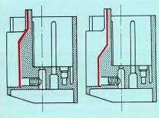

fig. 28 (left)     fig. 29 (right)


The profile of the cam in the throttle slide controls the action of the accelerator pump.

For example, cams having the operating ramp high up in the throttle valve (see figure 28) make the pump start to work immediately the throttle opens.

Operating ramps lower down in the slide delay the spraying action of the pump.

Having selected the cam type, to produce immediate or delayed pickup from engine idle, the pump jet size can then be chosen.


The size of pump jet selected determines the duration of fuel delivery, so the larger the pump jet used the shorter the pump spraying interval and vice versa. The quantity of fuel sprayed out has already been fixed.

Pump jet selection must be effected with the engine running with rapid full-throttle acceleration; under these circumstances the optimum jet size should allow the engine to pick up regularly and promptly, rapidly increasing engine speed in every acceleration-speed range.


3.7.3 - Piston-type accelerator pump
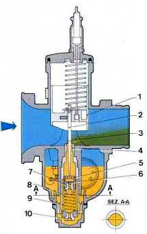

fig. 30

Figure 30 shows a simpler pump system than the one previously described, used on some other Carburetor models.

As shown in the figure, on opening the throttle (1), the tapered-needle (2) integral with it, releases the piston (5) with its perforated top, which rises, pushed by the spring (8), squirting fuel through the atomiser (4) directly into the main barrel (3). In the upstroke, the ball-bearing valve (6) closes and seals the hole (7).

On the downstroke, the needle pushes the piston (5) down, compressing the spring (8), while the ball valve (6) rises, unblocking hole (7) so that more fuel can again fill the chamber which has been formed above the piston.

The length of the chamber where the piston (5) moves, determines the amount of fuel which is pumped up into the main barrel (3).

The pump action is also affected by the length of the grooves (9) machined in the internal walls of the cylindrical chamber, where the pump piston moves (see figure 30).

When the throttle slide stops moving in any open position, the piston (5) also stops, stopping the pump action; the Carburetor therefore then works in the usual way. Fuel, which rises continuously from the float chamber by the normal partial- vacuum action and flows first through the main jet (10) and then up into the atomiser-needlejet (4) to tlg. 30 the main barrel (3), keeps the ball valve (6) open.


B A C K
I N D E X
N E X T